Soil tester measurement accuracy Two requirements for light source intensity When measuring different items, different colors of monochromatic light (such as red light, violet light, etc.) are required. This requires the use of different color filters to obtain the desired monochromatic light. However, different color filters have a great difference in the weakening effect of light intensity. The same intensity of incandescent light, the violet light intensity formed by the purple filter is much weaker than the red light intensity formed by the red filter. . Related Instruments: Soil Moisture Analyzer Soil Moisture Temperature Detector Soil Temperature and Humidity Recorder 98Mm Neck Size Jar Preform,98Mm Pet Preform,98Mm Wide Mouth,98Mm Wide Mouth Preform Heshan Yecheng Plastic Products Co.,Ltd. , https://www.plasticpreform.com
Not only the different color filters have an influence on the light intensity of the illumination sensor, but also the response of the photoelectric sensor to light of different wavelengths is also different. Figure 2 shows the relationship between the optical wavelength λ and the relative response of the sensor. It can be seen that the relative response of the sensor output voltage to red light (λ=650nm) is greater than that of the violet light (λ=450nm), that is, the sensor It is sensitive to red light and less sensitive to violet light.
The same result is caused by the two reasons, that is, the light intensity required for measuring with red light is small, and the intensity of light required for measuring with violet light is large. In this way, when the light intensity meets the requirements of the purple measurement, for the red light, the output of the photoelectric sensor is nearly saturated, and the measured result is inaccurate; when the light intensity meets the requirement of the red light measurement, the output of the photoelectric sensor is for the violet light. It is too small to meet the measurement accuracy requirements. Therefore, to meet the requirements of different measurement items, it is necessary to use different filters, so that the output of the photoelectric sensor can be in the linear range, which requires changing the light intensity of the light source according to the different colors of the filter, in fact, It is to change the current flowing through incandescent bulbs. This is the first requirement for light intensity to improve measurement accuracy.
In order to improve the measurement accuracy, the most important thing is that under the same measurement conditions, the photoelectric sensor should have a stable output. Theoretically, as long as the current through the incandescent bulb can be controlled, or the voltage across the lamp is constant, the light intensity of the bulb can be kept constant, and the output voltage of the photoelectric sensor should also be very stable. However, during the experiment, it was found that when the current through the bulb is constant, the output of the photoelectric sensor is not stable around a certain value, but it drifts in a very small range, often continuing to rise, and then continuing to decline. Repeatedly, this shows that the light intensity is essentially fluctuating. Therefore, the second requirement for light intensity is to maintain the dynamic stability of light intensity. 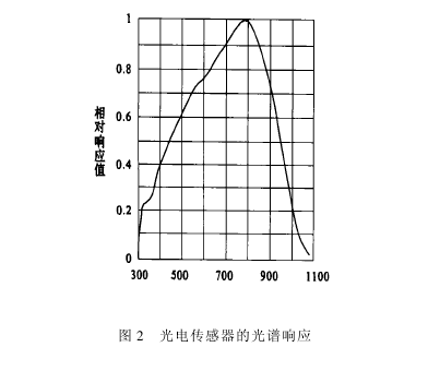
Soil tester light intensity control circuit In the application example mentioned in this article, the digital potentiometer and the ordinary MOSFET under the control of the single chip constitute the light intensity control circuit, the principle of which is shown in FIG. 3 . 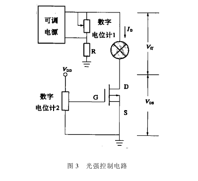
According to different measurement items, the digital potentiometer 1 is adjusted and the voltage applied to the light bulb and the MOSFET is changed. Different operating currents can be obtained to achieve the purpose of adjusting the light intensity.
When the bulb is operating at a certain operating current, such as when the operating point is on a curve in the constant current region of the MOSFET (see Figure 4), the output voltage of the photosensor always fluctuates slowly. After further experimental research and analysis, it is found that the voltage output of the photoelectric sensor has a linear relationship with the radiation of the light source. As long as the radiation level remains unchanged, the output voltage of the photoelectric sensor can be kept constant. In the case of the same light area, the radiation is not directly dependent on the current of the bulb, but is related to the luminous power of the bulb. In fact, when the MOSFET operates in the constant current region, the current ID flowing through the bulb does not change, and the resistance of the bulb changes with the temperature, causing the V lamp to change, the operating point of the MOSFET shifts left and right on the curve, and the output power of the bulb changes. Causes fluctuations in the voltage output of the photosensor. Therefore, to ensure that the output voltage of the photosensor is stable under certain measurement conditions, the luminous power of the lamp should be kept constant. How to make the bulb's luminous power always stable under the condition of relatively stable bulb current? Obviously, it is difficult to control this random variation artificially. However, the operating point of the MOSFET can be changed to make it work in the variable resistance region by using the MOSFET itself. The operating characteristics compensate for fluctuations in the ID and V lamps. See Figure 4 for specific principles. The digital potentiometer 2 adjusts the gate-source voltage VGS of the MOSFET to select a suitable operating curve for the MOSFET, and then adjusts the lamp voltage according to the requirements of the specific measurement item on the intensity of the light source, so that the MOSFET operates at a certain point in the variable resistance region, such as Point A in Figure 4. In this area, the drain current ID of the MOSFET increases linearly with the increase of the drain-source voltage VDS. For a certain VDS, the corresponding ID is available, then the output power of the light bulb P = ID × V lamp. Because the bulb's resistance varies slightly with the lamp temperature, when the temperature of the lamp increases, the lamp resistance R lamp increases and the voltage V lamp on the lamp increases, causing the VDS of the MOSFET to drop by itself, that is, the operating point is slightly curved along the curve. Moving down, the MOSFET naturally works with a new, slightly reduced ID, resulting in the P lamp = ID x V lamp remaining essentially unchanged, and vice versa. Facts have proved that this self-tuning method is effective and can maintain the output power of the bulb at a substantially constant level, thereby ensuring the stability of the output voltage of the photoelectric sensor. 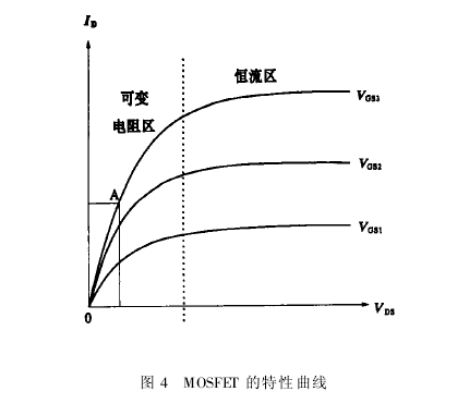 The light intensity control circuit is simple and easy to implement, and not only can adjust the light intensity according to different measurement items, but also can dynamically stabilize the light intensity during the measurement process, laying the foundation for high-precision measurement of soil components and other items. The experimental results show that the measurement accuracy error is less than 1%, which greatly exceeds the national standard. Finally, the accuracy of the spectrophotometric method was obtained and surpassed by inexpensive filter measurements.