Corn flour mill uses dry corn deskin and embryo removal technology, and the rate of leather embryo removal is relatively high. At present, China has the least occupied area, the highest degree of automation, the least investment and the most extensive processing equipment.
If you have any questions, please contact with us directly. Welcome you can visit our Factory.For inqury,Please send mail directly to us.
Corn Flour Machine,Corn Pulverizer Equipment,Corn Milling Machine, Corn Flour Milling Machine Shandong Hengyi kaifeng Machinery Co.,Ltd , http://www.xhykf.com
Second, the main steam pressure controlled object model The steam pressure regulation object production process shown in Figure 1, the object consists of five links (this article only briefly describes the characteristics of each link). 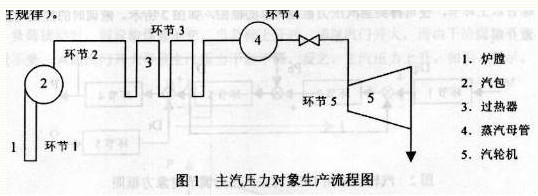
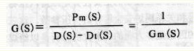
2. Endothermic Evaporation Section The total boiler heat absorption in this section consists of two parts, part of which is taken away by the superheater (D) and part of which is the incremental heat storage of the boiler (Pb). Its transfer function is: 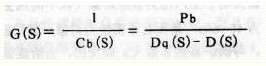
Pb - steam drum heat storage, as a function of drum pressure;
D - heat taken by the main steam flow;
Dq - total heat absorption.
3. The transfer function of the resistance section of the heating surface is: 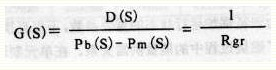
![]()
By synthesizing the above links, a block diagram of the main steam pressure controlled object can be obtained, as shown in FIG. 2 . The liquid control object is not introduced here. 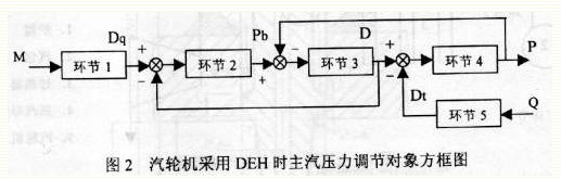
III. ANALYSIS OF DYNAMIC CHARACTERISTICS OF SUBJECTED STEEL PRESSURE-CONTROLLED OBJECTS From the above analysis of the main steam pressure objects, we can see that the main disturbances causing main steam pressure changes are the coal supply disturbance and the turbine load disturbance, which are analyzed separately.
1. The dynamic characteristics of the main steam pressure controlled object under disturbance of coal supply are analyzed. When the coal supply disturbance is assumed, the load is unchanged, and its object transfer function is: 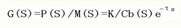
![]()
2. System design In the actual operation, CCS of our factory mainly operates in the way of the stove heel. The basic block diagram is shown in Figure 5. The basic composition of this coordination system includes two feedback regulation systems: the turbine electro-hydraulic fluid automatic control system (DEH) and the boiler main steam pressure automatic adjustment system (boiler main control). Its basic working principle is: The DEH system of the steam engine receives the actual load command signal given by LMCC as a given value, and then uses the microcomputer output signal after the logic operation processing with the actual load feedback signal to control the throttle opening of the speed control valve. Meet load requirements. The boiler master controls the deviation of the boiler main steam pressure and the given value and controls the speed of the coal feeder after logic calculation. The main steam pressure regulation system adopts power as a feedforward signal to overcome the delay caused by the inertia of the main steam pressure regulation object, speed up the adjustment process, and maintain the system stability. At the same time, the coal feed signal is accepted as the feedback signal of the inner loop, and the effect is to eliminate the influence of the coal feed disturbance on the main steam pressure. Therefore, the main steam pressure control system is a cascade control system with feed forward, that is, a compound regulation system. The coordinating system of the hearth machine mode, because of the rapidity of the load response and the necessary stability of the main operating parameters, and the adjustment of the adjustment system are relatively convenient, so the operation of the four units in our factory is adopted. 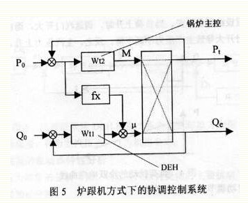
1. The main control boiler boiler control diagram shown in Figure 6. The main boiler control consists of the following components.
(1) The formation of feedforward signals The selection of reasonable feedforward signals can greatly improve the quality of the adjustment. The feedforward signal of the main steam pressure regulation system of our factory is formed by the pressure control of the speed control stage: I=P1*Pts/Pt, where P: is the pressure of the speed control stage; pTS is the given value of the steam pressure; Pt is Main steam pressure. The use of governor stage pressure can quickly reflect the load change, and this feedforward signal fully considers the main steam pressure and its given value, and can fully reflect the variation load and the main steam pressure deviation factor, so that the feedforward signal is in the system. The role is more practical. It can increase the amount of coal before the change of main steam pressure under load changing conditions and eliminate the disturbance caused by load changes. In the practice of large-scale peak shaving and frequency modulation, this feedforward signal is used to minimize the effect of load changes on the main steam pressure and ensure the operation of the boiler. 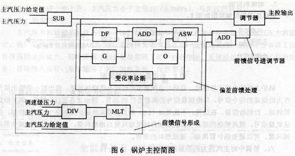
(3) The adjustment function of the main control of the boiler performs PI (proportional-integral) operation on the main steam pressure deviation signal, performs DF (differential) operation on the feed-forward signal, and superimposes the main control output. When the rate of change of deviation is large (Δp is greater than 0.016 MPa/s), the above-mentioned main control output must also be added with the deviation gain and deviation differential signal to speed up the adjustment process and improve the adjustment quality. Calculated as follows:
When the deviation change rate is less than 0.016MPa: Yo=KAp+∫ΔPdt+PI*Pts/Pt
When the deviation change rate is greater than 0.016 MPa: Yo=KAp+∫ΔPdt+Pi*Pts/Pt+ΔP*G+TdS*Δp
In the formula, Yo is the main control boiler of the boiler; â–³P is the main steam pressure deviation. The output of the boiler master regulator is sent to the coal feeder regulator.
2. Coal feeder control coal feeder logic control diagram shown in Figure 8. 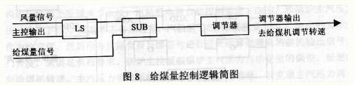
6. Additional control of the main steam pressure in the coordination In order to reduce the main steam pressure fluctuations, the coordinating system under the operating mode of the furnace to maintain the main steam pressure is shown in Figure 9.
From the foregoing discussion, it is known that the main steam pressure regulation object has a large delay and a long adjustment time, which easily leads to main steam pressure fluctuations. Therefore, when the main steam pressure is deviated, we use the method of sacrificing the load to maintain the main steam pressure and reduce the fluctuation. That is, we use the speed control valve to adjust the main steam pressure. The specific method is to increase or decrease the actual load command by 3MW (the main steam pressure is higher than the fixed value 0.26MPa, lower than 0.56MPa) to achieve the purpose of addition and subtraction, as shown in Figure 9. 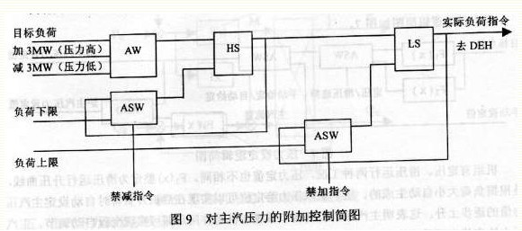
7. Conclusion The main steam pressure automatic adjustment system is used as the main adjustment system for boiler operation. Its main task is to maintain the stability of the main steam pressure. After adopting Hitachi's HIACS-3000 system as a regulating device, our plant has a strong ability to adapt to varying load conditions such as peaking and frequency modulation. At the same time, the DEH system is used to achieve coordinated control of the furnace. After several rounds of debugging, the system has been increasingly perfected, and the automatic input has been good. It has basically adapted to the requirements of various operating conditions of our plant units.
Corn flour mill can process corn, such as cleaning, peeling, removing embryos, removing roots, removing black umbilicus, crushing, picking, grading, polishing and selecting. It is suitable for small processing households to be used for external processing.

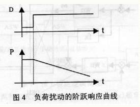
Theoretical Analysis of Main Steam Pressure Control System
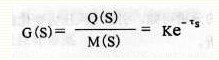
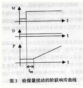
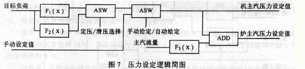
I. Introduction The boiler main steam pressure is an important parameter to characterize the operating status of the boiler. It not only directly relates to the safe operation of the boiler equipment, but also whether the steam pressure is stable reflects the energy supply and demand relationship in the combustion process. In the unit system operation state, the steam pressure value of the boiler is related to the operation state and operation mode of the unit, that is, the steam pressure control of the boiler and the load control of the steam turbine influence each other. Moreover, as far as the boiler is concerned, the main task of the combustion process control is to maintain the stability of the steam pressure. The related parameters include the oxygen amount signal that maintains the economy of the combustion process and the negative pressure parameters that relate to the safe operation of the boiler. These three parameters adjust each other. influences. Therefore, there are many factors affecting the stability of the main steam pressure. The analysis of this paper is based on the disturbance of the coal supply volume, and other changes in response to the induced wind are used to respond to changes. Steam consumption (representing load) of the steam turbine is used as external load disturbance. As the main steam pressure control system design and analysis basis. In our plant practice, the main steam pressure system as part of the coordinated control system, we must also pay attention to the load factor to form a complete main steam pressure control system. 1. The transfer function of coal supply M and heat release Q in the combustion process is: It can be seen from the equation that this process is a pure delay link, and K is the combustion link factor. In the formula, Cb, the heat storage coefficient, reflects the heat storage capacity of the boiler; 4. Steam flow link The link between the main steam pressure Pm, the boiler evaporation volume D, and the total steam consumption Dt of the steam turbine is the link transfer function: 5. The relationship between the main steam pressure and steam consumption in our plant's DEH system, due to the use of power control to maintain the steam turbine power for a given value, so the steam consumption is only related to the load and has nothing to do with the main steam pressure, ie the load changes for the main steam Pressure is an external disturbance and the formula is as follows: In the formula, Dt is the main steam flow; Pt is the main steam pressure. In Figure 2, M is the coal supply quantity; P is the main steam pressure: Q is the unit load. It can be seen from this formula that the main steam pressure controlled object (hereinafter referred to as the main steam object) under the disturbance of the coal supply quantity is a delayed integral component whose delay time Ï„m is approximately 40-60s, which is an object without self-balancing capability. The response curve is shown in Figure 3. The integration speed of the steam pressure object is Km/Cb, which is inversely proportional to the boiler thermal storage coefficient Cb. When the coal supply increases, the main steam pressure rises, and the DEH shuts down the throttle opening to keep the power constant. This causes the main steam pressure to increase. As a result, the disturbance to the coal supply causes an energy imbalance. The excess energy is accumulated in the boiler pipe, so that the main steam pressure becomes integral and the main steam pressure drops. 2. The dynamic characteristics of the main steam pressure controlled object under load disturbance can be seen from Fig. 2. When the coal supply quantity is constant, the main steam flow rate D does not change, and the load Q and the main steam pressure P have a negative integral relationship. Since the link 4 is the integral and the link 5 is the proportional link, the main steam pressure is the integral of the difference between the main steam flow and the unit load. The transfer function is: When the load is disturbed, it is assumed that the amount of coal is not changed. When the load rises, the speed control valve opens large, and because the same amount of coal is fed, the evaporation does not change, and the main steam pressure decreases continuously when the speed control valve opens. On the contrary, the main steam pressure rises. As shown in Figure 4. Fourth, the main steam pressure automatic adjustment system design program 1, the system overview Unit system large capacity thermal power unit often only with the basic load, and now must be based on grid frequency deviation and load requirements of the central dispatching requirements to participate in the grid peaking frequency regulation, and even In the case of some auxiliary units of the unit and local failure (such as coal feeder RB), the unit operation must still be maintained. For such a unit, it is required that the range of load of the unit is large, and the minimum load that can be operated stably is low. In August, when the plant peak load reached 90MW, and there is a good load adaptability in the entire peak-shaping range, that is, it can bear a higher load change rate, and its main operating parameters (main steam pressure) during the load change process It is relatively stable. Our factory has followed this principle in coordinating the design of the main steam pressure automatic adjustment system. When the unit meets the variable load requirements while maintaining the boiler main steam pressure, the unit is viewed as a whole. The furnaces meet the requirements of the grid load and maintain the stability of the main steam pressure by means of respective adjustment means, such as the throttle opening and feed rate. In the control system design of our plant, the load feedforward signal and the coordination signal are used to allow the machine to change in accordance with the requirements of the grid load at the same time, and to accept the load command and coordinate the control according to the deviation of the main steam pressure. Such a control system is a coordinated control system (CCS), and the main steam pressure control system is a boiler main control of CCS. V. Main Steam Pressure Regulation System Analysis The main steam pressure regulation system is composed of two parts: boiler control and coal feeder control. (2) pressure set value form pressure logic diagram shown in Figure 7 The unit has two conditions of constant pressure and sliding pressure, and the pressure setting is not the same. F2(x) is set as the sliding pressure boosting curve, which is automatically generated according to the load size. This main steam pressure setting value can automatically set the main steam pressure value to increase gradually when the starter is under load. This indicates that the main steam pressure automatic adjustment system can realize full automatic adjustment after the unit is connected to the grid. The main steam pressure setpoint can also be manually specified, but only the steam turbine main steam pressure setpoint is given. The main steam pressure of the boiler takes into account the pressure difference formed by the opening of the main automatic valve (regulating door), so the function of the main steam flow is introduced to correct it: P furnace = F(x)*D+P machine, F(x) The relationship between main steam flow and pressure difference. The main control signal output from the main control of the boiler must be subjected to a small selection module operation with the total air volume signal, and a smaller output signal is selected as the command signal for the coal supply amount, and the deviation from the coal supply signal is PI-calculated, and the output is sent to each operation. To the coal machine, adjust the speed of the coal feeder and control the coal supply. Here, the purpose of the small selection process (LS) is to achieve boiler excess air and fuel control, ensure the oxygen signal, and improve the economy of combustion. When the load is increased, the amount of fuel is increased after the amount of air is increased first, and then the amount of air is reduced after the load is reduced to avoid the black smoke of the boiler and the waste of fuel. 2. Load prohibition and prohibition function When the main steam pressure deviation is further enlarged, in order to ensure the safe operation of the unit, the function of load prohibition and prohibition is set. According to the characteristics of the main steam pressure regulation object, when the load is increased, the speed control valve opens, causing the main steam pressure to decrease. If the main steam pressure is very low, it will inevitably threaten the stable operation of the unit; otherwise, the main steam pressure It will increase dramatically and become more dangerous. This function can solve this problem. When the main steam pressure is greater than the set value (each plant is 0.6MPa), the prohibition command in Fig. 9 is set to "1". If the target load is reduced, the high-selection module (HS) will select the current load to maintain the load. To prevent the main steam pressure from further increasing due to load shedding. When the main steam pressure is less than the fixed value (0.7 MPa), this is the opposite of this process.